Configuring an Incremental Encoder on the NDrive Z1 with a 5010 360kV BLDC Motor: Step-by-Step Tutorial
This tutorial walks you through configuring an incremental encoder on the NDrive Z1. You'll run index search and calibration, then tune the position and velocity gain controllers. Finally, you'll validate everything with a position control move.
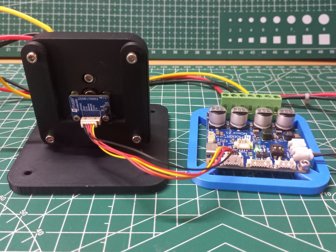
Introduction
Unlike an absolute encoder, an incremental encoder has no idea where it is the moment power is applied. It only reports relative motion through quadrature pulses on its A and B channels, plus a single index (Z) pulse once per mechanical revolution. That means before the driver can trust the encoder's position for closed-loop control, it needs to find that index pulse and use it to establish a known reference point.
Wiring
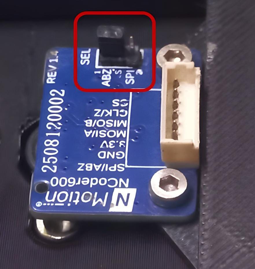
The image shows the incremental encoder configured with the SEL switch set to ABZ mode rather than SPI, as required for incremental encoder operation.
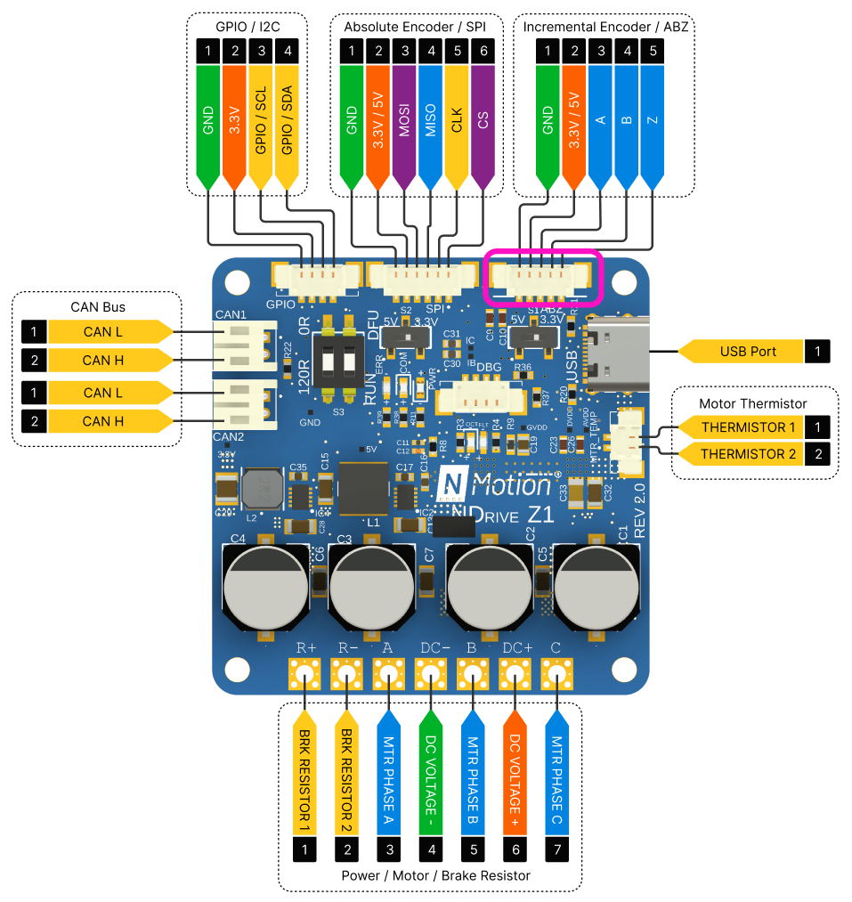
The 5-pin JST connector must be wired from the incremental encoder to the NDrive's ABZ port. When making this connection, ensure alignment starts from the ground pin, as one pin on the NCoder 600 side will remain unconnected.
A note on PPM to CPM conversion
In this tutorial, for the incremental encoder we will be using the Nmotion's NCoder 600 which is configured for a certain number of pulses per mechanical revolution, or PPM. The NDrive Z1's configureMotorEncoder call, however, expects a resolution figure in counts per mechanical revolution, or CPM which is the number of distinct position states the driver's quadrature decoder can resolve per revolution. This isn't the same number as PPM.
Quadrature decoding reads both the rising and falling edges of both the A and B channels, which multiplies the encoder's raw pulse count by 4:
CPM = PPM × 4
So an NCoder 600(or an MA600 equivalent) configured to output 512 PPM gives the driver:
512 × 4 = 2048 CPM
That 2048 figure is the resolution value the driver expects.
If you are using an incremental encoder other than the MA600, identify its PPM and substitute to find the right CPM.
Configuring the Incremental Encoder and Finding the Index
With the incremental encoder wired and set to corresponding CPM, the next step is to tell the driver about the encoder, locate its index pulse, and run calibration so the motor's phase and encoder offset are correctly established.
For detailed information on CLI commands, refer NMotion-CLI
- 1
Power Configuration:
- 2
Motor Configuration:
- 3
Encoder Configuration:
The MA600 in incremental mode is encoder type 2 (TYPE_INCREMENTAL) with a resolution of 2048 counts per revolution. Refer to the table to identify the encoder type applicable to your setup.
- 4
Run the Calibration Sequence:
With the index found, calibration estimates the motor's phase resistance and inductance and computes the motor encoder offset relative to the index reference.
warningIf an error is triggered, the error LED (RED) turns on. Check the specific error code with
Driver_10_ttyACM0.getErrorCode()and refer to the Error Handling section before continuing. - 5
Save Configuration
Index search must complete successfully after saveConfigurations is called. Unlike an absolute encoder, the incremental encoder loses its position reference on every power-down, so this step has to be repeated any time the driver loses and regains power and not just the first time it's configured. Skipping it will result in an invalid state error.
Tuning the Control Loops
With the encoder configured, indexed, and calibrated, the driver is ready to have its position and velocity loops tuned before any control command is implemented. For detailed tuning guides, refer this as PID can vary differently in accordance with the motor used.
- 6
Set the Position Gain Controller:
- 7
Set the Velocity Gain Controller:
- 8
Save:
warningSaving writes to non-volatile memory and triggers a reboot. The encoder configuration and gain settings only take effect after this reboot completes. Non-volatile memory has a limited number of write cycles, so avoid saving more often than necessary.
Verify with Position Control
Because the system reboots, the incremental encoder's index reference is gone the moment the driver comes back up. It has to be re-established before the position controller can be trusted.
- 1
Re-run Index Search:
Index searching
Operation
After index search, calibration, and gain tuning, the motor was commanded through the position controller to 90° and held there, tracking the commanded setpoint using the incremental encoder's feedback.
Ensure safe and reliable operation of the motor controller by monitoring the error LED and checking the error codes reported by the controller throughout the move.
With the enocder configured as an incremental encoder at its specific CPM, index search completed, and the position and velocity loops tuned, the 5010 360kV BLDC motor is calibrated and ready for closed-loop position control through the NMotion CLI Tool.
For more details, check out our documentation or reach out to our support team!
 NMotionTM is a sub-brand of Nawe Robotics