Configuring an Output Encoder and Gear Ratio on the NDrive Z1 with a 5010 360kV BLDC Motor: Step-by-Step Tutorial
This tutorial provides a step-by-step walkthrough to configure an output encoder and gear ratio on the NDrive Z1, run calibration and encoder matching, and validate it all with a trapezoidal trajectory test.
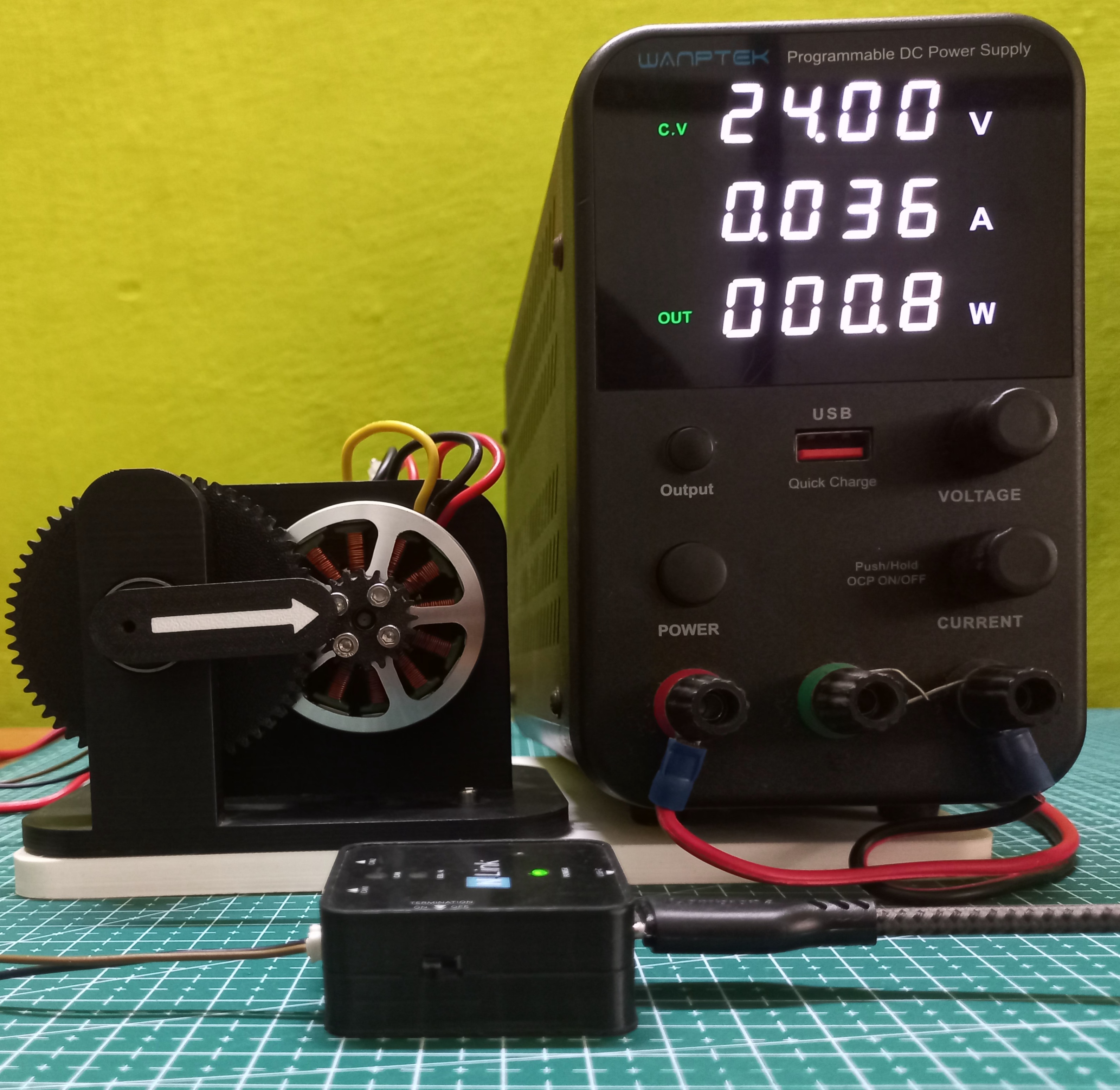
Introduction
When a gearbox sits between a motor and its load, the motor's own encoder can't tell you where the output shaft actually is. You need a second encoder at the output, a configured gear ratio, and an encoder matching step that ties the two together so the driver's position control stays accurate.
This post walks through configuring an output encoder and gearbox ratio on the NDrive Z1, running calibration and encoder matching, and then validating the setup with a trapezoidal trajectory test, including a full power cycle in the middle to confirm everything held.
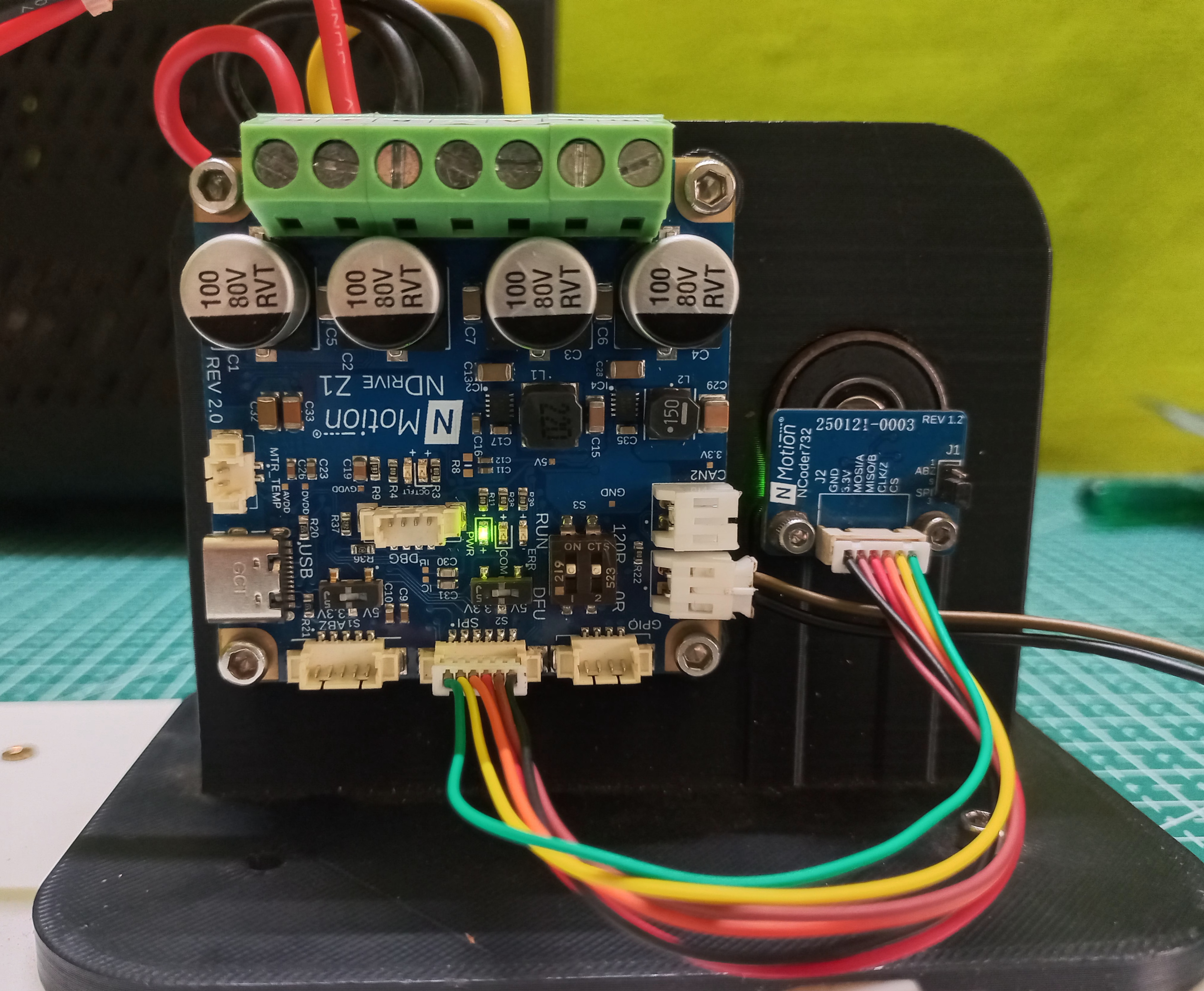
This tutorial assumes the 5010 360kV BLDC motor is already wired, mounted, and calibrated against the NDrive Z1's onboard encoder. If you haven't done that yet, start with the 5010 360kV integration tutorial first, then come back here to add the output encoder and gear ratio.
Configuring the Output Encoder and Gear Ratio
With the motor encoder already calibrated, the next step is to configure the external output encoder, tell the driver the gear ratio between motor and output, and re-run calibration and matching so the two encoders agree on where the output shaft actually is.
- 1
Configure the Output Encoder:
The output encoder is an external MA732 absolute encoder, mounted on the gearbox output shaft (not the motor shaft). The MA732 belongs to the SPI absolute-encoder family, so its encoder type is 4 (TYPE_SPI_ABS_MAXXX), and it has 14-bit resolution: 16384 possible position values per revolution.
- 2
Set the Gearbox Ratio:
With both the motor encoder and output encoder configured, the driver still needs the gear ratio between them so it can compute output-shaft position from motor-encoder counts.
- 4
Run the Calibration Sequence:
This re-measures motor phase parameters and re-determines the motor encoder offset. During the sequence, the driver draws current and emits a short beep during the inductance-measurement phase, then rotates the motor slightly in both directions to establish the encoder offset.
It runs the calibration sequence. During calibration, it estimates the phase resistance and phase inductance of the motor, computes the motor encoder offset, verifies the configured pole pairs of the motor and the resolution of the encoder, and matches the output encoder direction to the motor encoder.
warningSaving writes to non-volatile memory and triggers a reboot. The output encoder and gearbox settings only take effect after this reboot completes. Non-volatile memory has a limited number of write cycles, so avoid saving more often than necessary.
infoIf an error is triggered, the error LED (RED) turns on. Check the specific error code with
Driver_10_ttyACM0.getErrorCode()and refer to the Error Handling section before continuing to encoder matching. - 5
Match the Encoders:
Calibration alone only re-establishes the motor encoder's own offset. It does not relate the motor encoder to the output encoder. That relationship is set separately, by running encoder matching.
noteEncoder matching synchronizes the two encoders so the position the driver reports at the output (motor encoder value scaled by the gear ratio) matches where the output shaft is actually sitting. Skipping this step, with both encoders configured, risks the driver commanding motion based on a mismatched reference frame. Do not proceed to trajectory control until this step completes with no errors. This step must be performed every time the system is turned on, unlike the calibration sequence, which is only required once.
Verify with a Trajectory Move
With the output encoder configured, the gear ratio set, and both calibration and matching complete with no errors, the setup can be validated with a trapezoidal trajectory move, followed by a full power cycle to confirm the configuration actually persisted.
- 1
Command a Move:
Move the output from 0° to 180° along a trapezoidal velocity profile, using
angle,max_vel,accel, anddecelin degrees and degrees/s². - 2
Power Cycle the Driver:
Switch the power supply off, then back on. Not a software reboot. This confirms the saved calibration and matching actually persisted in non-volatile memory through a real power-down, rather than only having held in volatile state.
- 3
Re-run Encoder Matching:
noteRe-matching after a power cycle re-confirms the motor-to-output relationship is still consistent before you trust the driver with another move. This is a repeat of the Match the Encoders step above, not a new command.
- 4
Command the Return Move:
Operation
After calibration and encoder matching, the actuator was commanded through the trajectory controller, moving from 0° to 180° and back to 0° at a speed of 300 degrees per second.
Ensure safe and reliable operation of the motor controller by monitoring the error LED and checking the error codes reported by the controller throughout the move.
With the gear ratio set to 3:1 and the output encoder configured as an MA732 running at its full 14-bit resolution, the 5010 360kV BLDC motor and gearbox output are now synced and ready for use. The system is configured to use the onboard absolute encoder for the motor side, power handling is set up correctly, and the driver is calibrated and matched through the NMotion CLI Tool.
For more details, check out our documentation or reach out to our support team!
 NMotionTM is a sub-brand of Nawe Robotics