Connecting Hall Effect Sensors on a Hub Motor with the NDrive Z1: Step-by-Step Tutorial
This tutorial walks you through connecting the Hall effect sensors on a hub motor. You'll set up and fine-tune the motor's encoder reading on the NDrive Z1, then validate everything by watching for warning/error signals while the motor is spinning.
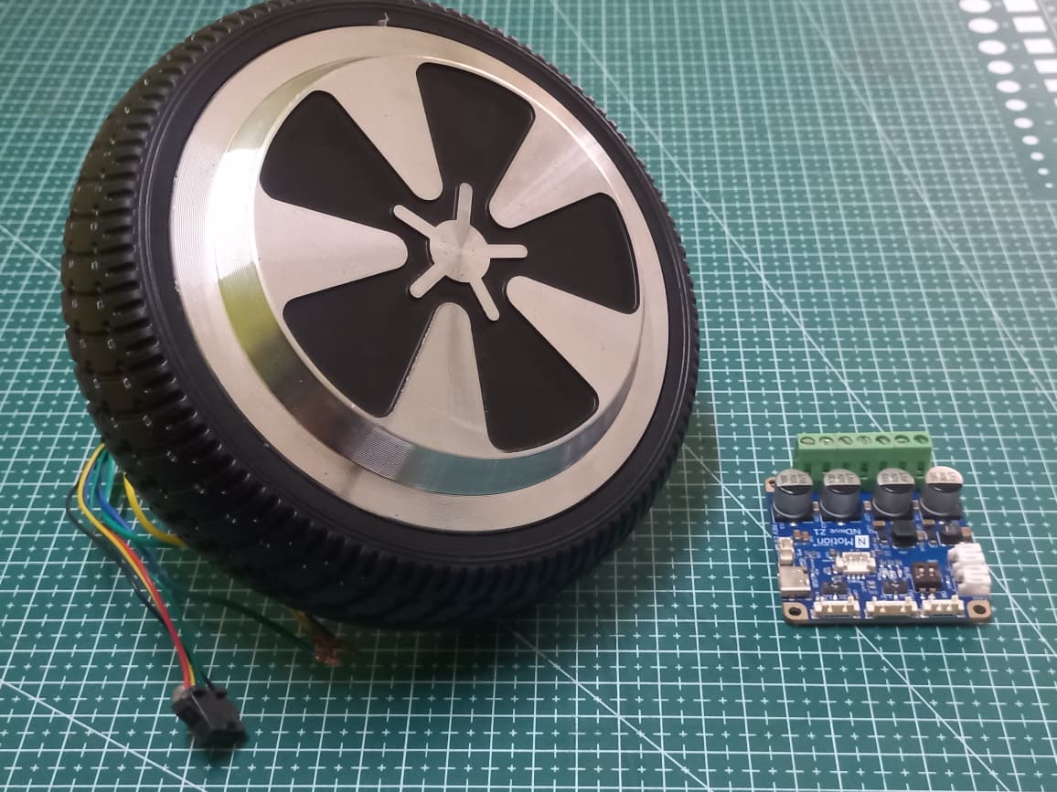
Introduction
Commutating a brushless hub motor requires knowing where the rotor is at any given instant. Hall effect sensors are the most common way to get that position feedback cheaply and reliably: three sensors mounted around the stator toggle high or low as the rotor's magnets sweep past, producing a repeating pattern the driver uses to commutate the motor.
This post walks through identifying the Hall sensor, wiring the required pull-up filtering, configuring the motor encoder and running calibration through the driver, and validating the setup by checking for illegal states and signal errors while the motor turns.
This tutorial assumes the hub motor is already mechanically mounted and the Hall sensor lines are accessible for wiring. If you haven't identified your sensor's pinout and output type yet, check the datasheet first, this tutorial picks up from there.
Wiring the Hall Bridge
Before configuring anything in software, the Hall sensor lines need to be wired with proper pull-ups and noise filtering. Get the physical layer right first, then move on to configuring the driver.
Add Pull-Up Filtering
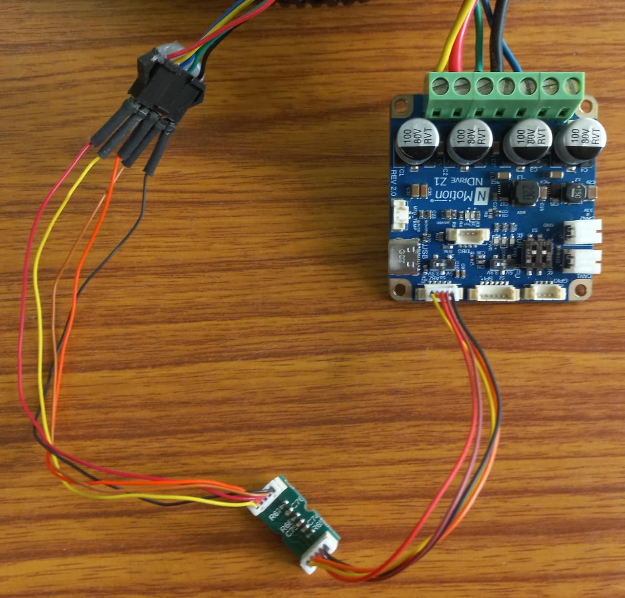
Connect the Hall sensor's power and ground pins to the matching power and ground terminals on the pull-up board.
Most Hall sensors used in motors are open-drain outputs: they can only pull a signal line low, not drive it high. Each of the three Hall lines needs a pull-up resistor to rest high until the sensor pulls it low, and in practice this is implemented as a Hall bridge, a resistor-capacitor network per line, where the resistor provides the pull-up and the capacitor filters switching noise from the motor's commutation currents.
Skipping the filter capacitor risks noisy transitions being read as illegal Hall states, especially at higher commutation currents. Wire the full RC network, not just the resistor.
Configuring the Motor Encoder and Checking Hall States
With the Hall bridge wired, configure the motor encoder parameters on the driver, save the configuration, and run calibration.
- 1
Set the Motor Encoder Parameters:
- 2
Configure the Motor Encoder:
The sensor type (20, matching the part identified earlier) and resolution (90, from the 6x pole pair multiplier) are passed together to configure the motor encoder.
- 3
Save the Configuration:
warningSaving writes to non-volatile memory and triggers a reboot. The encoder settings only take effect after this reboot completes. Non-volatile memory has a limited number of write cycles, so avoid saving more often than necessary.
- 4
Check the Hall Encoder State:
Check out the Hall sensor's encoder state to confirm whether the hall states are working properly.
Turn the hub motor by hand through one full revolution while calling
getHallEncoderState()repeatedly. The readings should only ever be values from 1 to 6, and 0 or 7 should never appear as they are considered as illegal states. The values follow the sequence 1→3→2→6→4→5, or the reverse (5→4→6→2→3→1).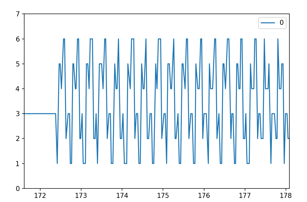
- 5
Run the Calibration Sequence:
The driver performs motor calibration, Hall polarity calibration, and encoder offset calibration in sequence.
infoIf an error is triggered, the error LED (RED) turns on. Check the specific error code with
Driver_0_COM6.getErrorCode()and refer to the Error Handling section before continuing.Once calibration is complete, call
getHallEncoderStateCounts()once and confirm there is no error status and zero counts on the two illegal states. - 6
Save:
Reading Hall Feedback
Operation
After wiring the Hall bridge, configuring the motor encoder, and running calibration, the driver was polled continuously while the hub motor was rotated by hand through several full revolutions.
The Hall state cycled through 1 to 6 as expected on each revolution, and getHallEncoderStateCounts() consistently returned RETURN_OK with zero counts on the illegal states throughout, confirming clean signal integrity through the pull-up filtering.
With the sensor identified, the Hall bridge wired, and both the state and the state counts reading cleanly, the hub motor's Hall feedback is ready to be used for commutation.
For more details, check out our documentation or reach out to our support team!
 NMotionTM is a sub-brand of Nawe Robotics