Integrating the NDrive Z1 with a 3536 BLDC Motor and S38 P223 Gearbox : Step-by-Step Tutorial
This tutorial provides a step-by-step procedure for connecting and configuring a 3536 BLDC motor with an S38 P223 gearbox using the NDrive Z1 and its onboard absolute encoder.
Introduction
This tutorial provides a step-by-step procedure for connecting and configuring the 3536 BLDC motor with an S38 P223 gearbox using the NDrive Z1 and its onboard absolute encoder. It covers hardware wiring, CAN communication setup and initial parameter configuration using the NMotion CLI Tool.
The procedure also includes setting the gear ratio so that position and velocity are reported at the gearbox output shaft rather than the motor shaft, followed by calibration for closed loop operation. Upon completion, the system will be calibrated and ready for stable and precise motion control.
What You Need
Before diving into wiring and configuration, make sure you have all the essential components and tools required to integrate the NDrive Z1 with the S38 P223 gearbox paired with the 3536 BLDC motor.
NMotion Components
- NDrive Z1 Motor Driver
- NLink Adapter (for USB/CAN interface)
- NMotion CLI Tool (for configuration)
Electronic Parts
- 3536 910kV Brushless Motor integrated with S38 P223 gearbox (24V rated, 7 pole pairs)
- Wires [16 AWG wire for DC+(Red) and DC-(Black)]
- CAN cables (2-pin JST PH, 2mm pitch)
- Type C USB Cable
General Parts
- 3D-Printed Mount for the Motor-Driver Setup
- 3D-Printed Magnet holder
- 3D-Printed Spacer
- 3D-Printed Driver Cover
- 6x2.5mm Diametrical Neodymium Magnet
- SHCS Allen Bolt M3x16mm x4
- Button Allen Bolt M3x30mm x4
- SHCS Allen Bolt M2x6mm x3
- M3 Brass inserts x4
Tools and Supplies
- Allen Key 2mm, 2.5mm
- Screw Driver
- Wire Stripper
- Power supply (12–48V)
For clarity, treat the 3536 910kV Turbo BLDC motor and the S38 P223 gearbox as a single combined assembly. Throughout this guide, this assembly will be referred to as the geared 3536 BLDC.
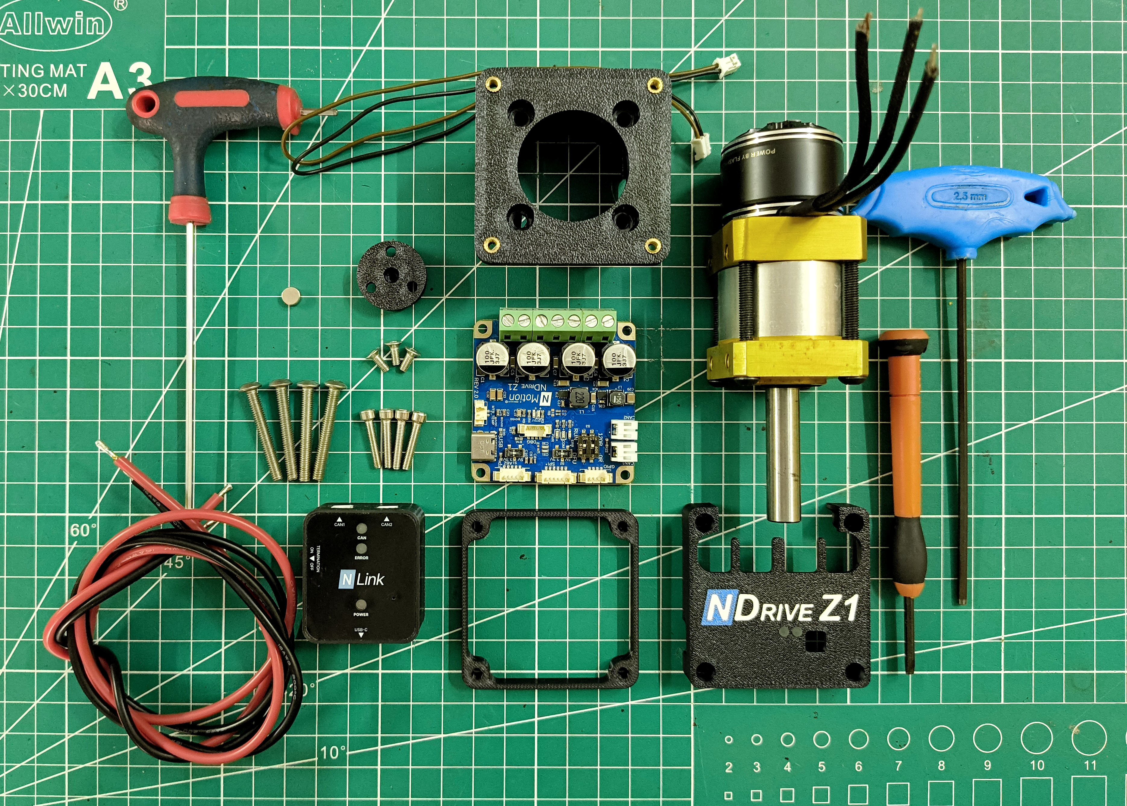
Hardware Setup and Connections
With the components in place, the next step is to connect the S38 P223 geared 3536 BLDC motor and the power supply to the NDrive Z1. This section walks you through how to connect the geared 3536 motor to the NDrive Z1, ensuring the wiring is correct, the connections are secure, and the system is ready for calibration and further configuration.
- 1
Mount the Magnet on the 3536 BLDC Motor:
Insert the 6 × 2.5 mm neodymium magnet into the magnet holder and make sure it is fully seated. Once the magnet is in place, mount the magnet holder axially onto the rear of the 3536 BLDC motor using three M2 × 6 mm SHCS Allen bolts. Ensure the magnet remains exposed and the bolts are tightened into the correct threaded holes.
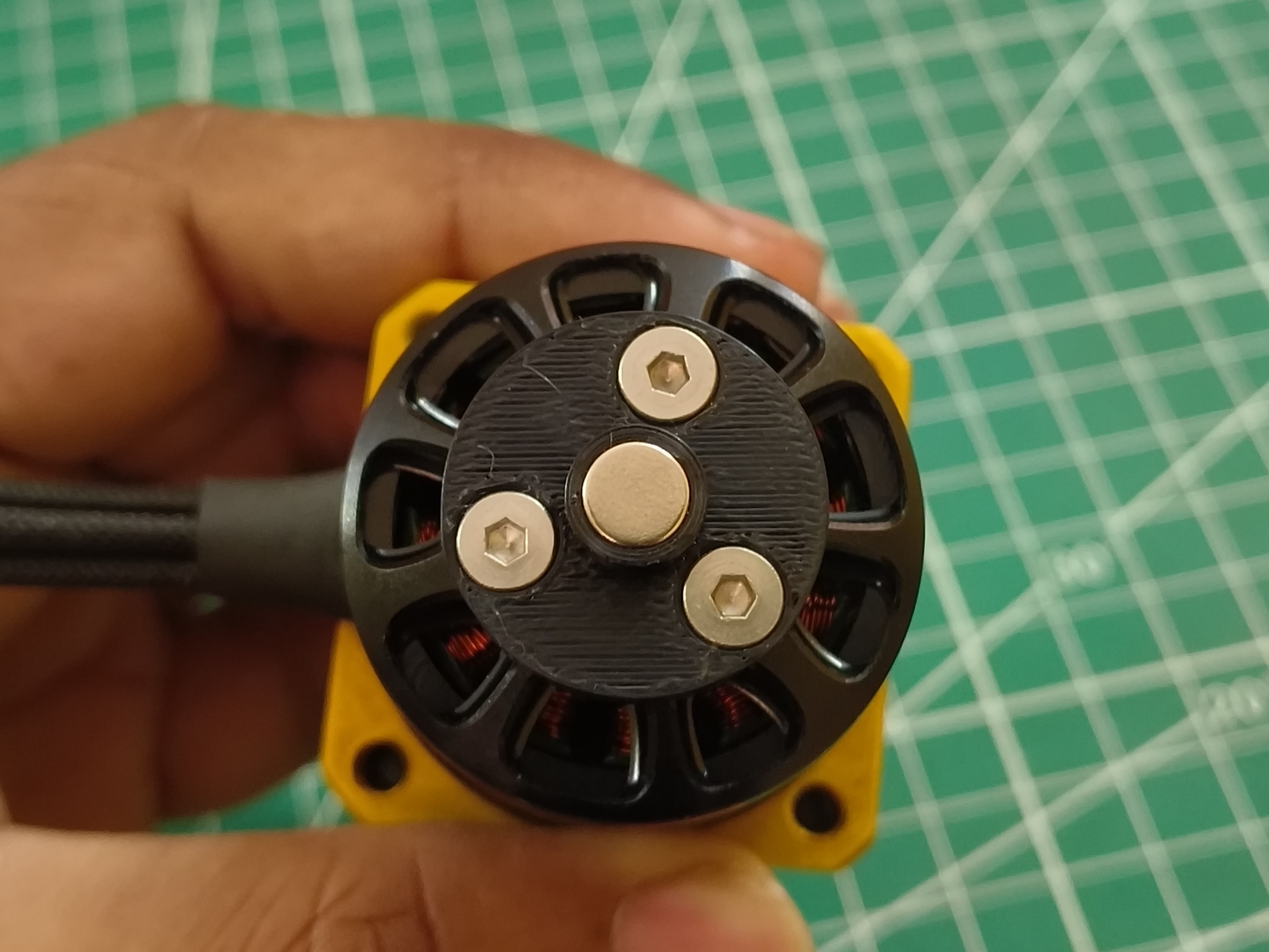
Magnet holder mounted over the rear shaft. - 2
Mount the 3536 BLDC Motor to the 3D-Printed Holding Mount:
Slip the motor into the 3D-printed holding mount and align it so that the opening for the motor phase wires is positioned correctly. Secure the motor using four M3 × 30mm button-head Allen bolts, making sure each bolt threads evenly into the corresponding holes on the gearbox assembly.
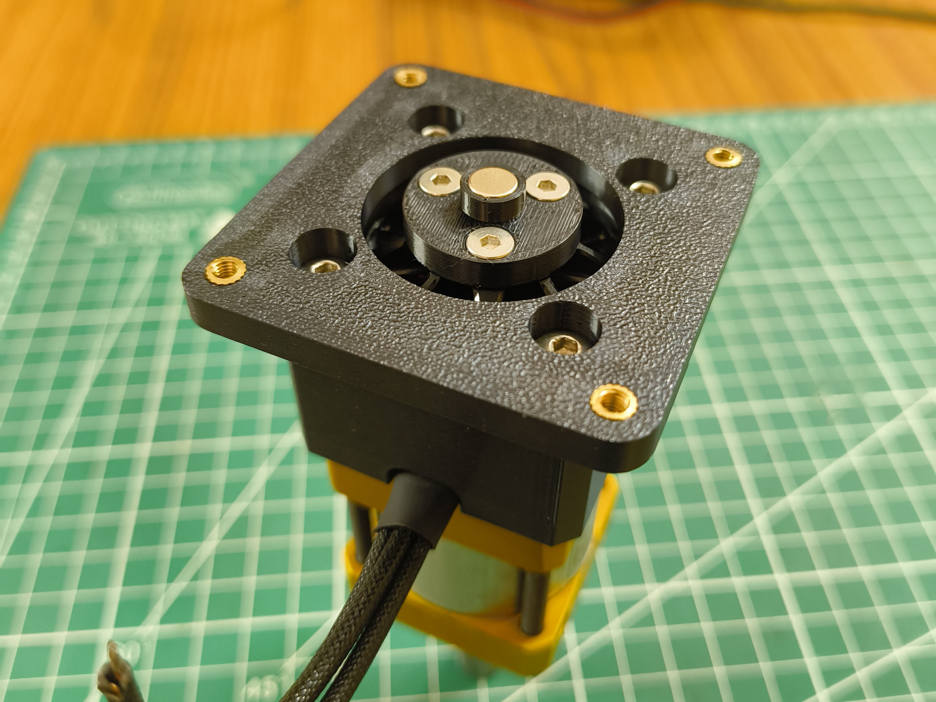
BLDC Motor Secured to 3D-Printed Mount. - 3
Secure the NDrive Z1 onto the 3D-Printed Mount:
Begin by installing the M3 brass inserts into the designated holes on the 3D-printed holding mount. Once the inserts are fully seated, place the 3D-printed spacer over the mount, followed by the NDrive Z1, and then the 3D-printed driver cover. These components stack in this order and are secured using four M3 × 16mm SHCS Allen bolts. Make sure all parts are properly aligned before tightening the bolts, and ensure the NDrive Z1 is positioned so the motor phase wires line up with the connection ports on the driver.
CRITICALBefore fully tightening the bolts, check the MA732 encoder IC (underside of the NDrive Z1) against the target magnet:
- Air gap: ≤1 mm (optimal 0.5–1.0 mm)
- Coaxial offset: within ±0.5 mm of IC center
- Polarity: diametrically magnetized (axial = calibration failure)
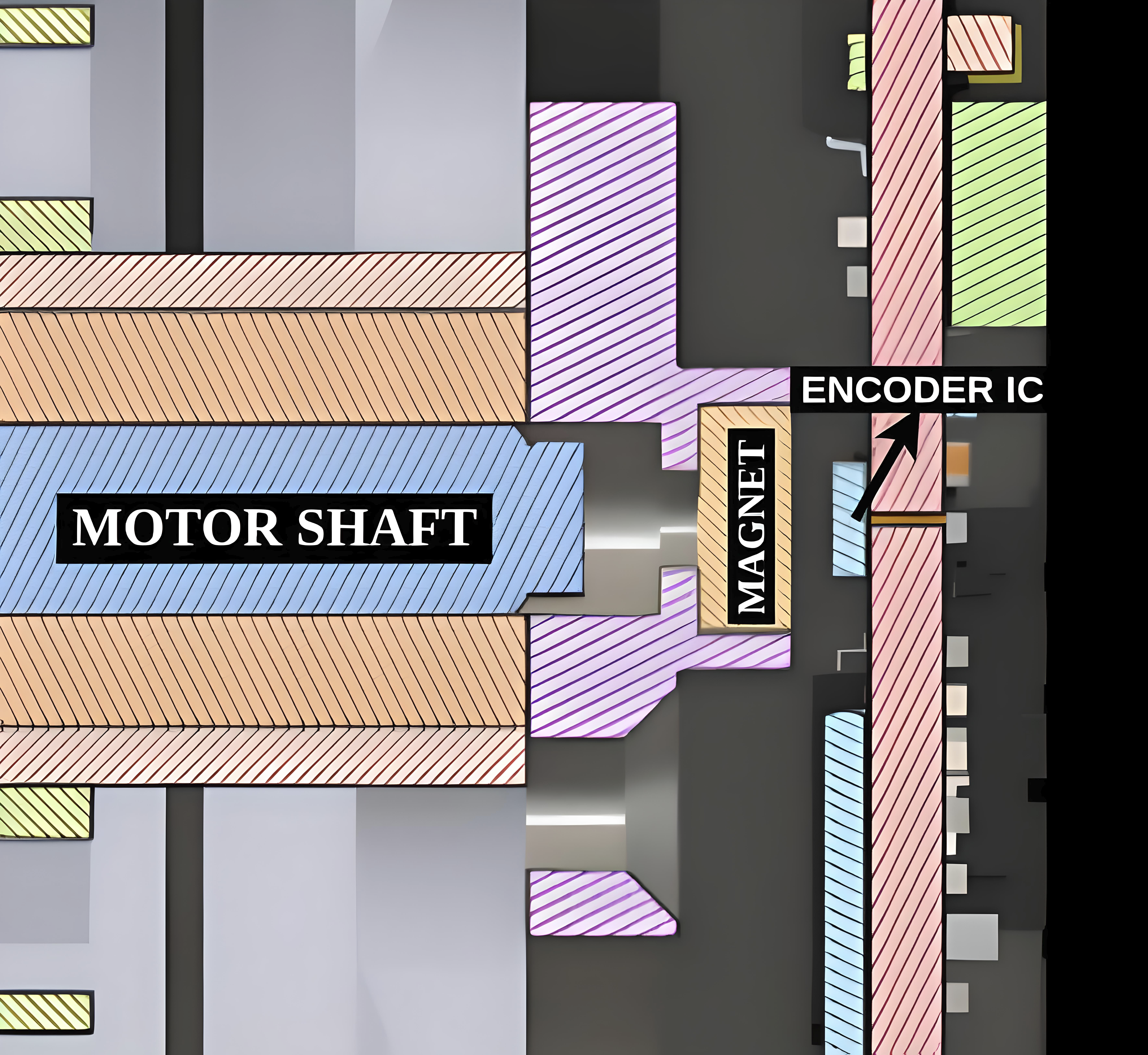
Magnet and NDrive's Encoder IC distance should be at most 1 mm.
- 4
Connect the Motor and Power Wires:
Wire the three motor phases from the 3536 BLDC Motor to the NDrive Z1’s motor terminals A, B, and C. The order isn’t critical for this setup.
Connect the Positive of the Power Supply to DC+ and the Negative to DC- .
dangerEnsure that the power connection is made correctly, as a reverse polarity connection can damage the driver board.
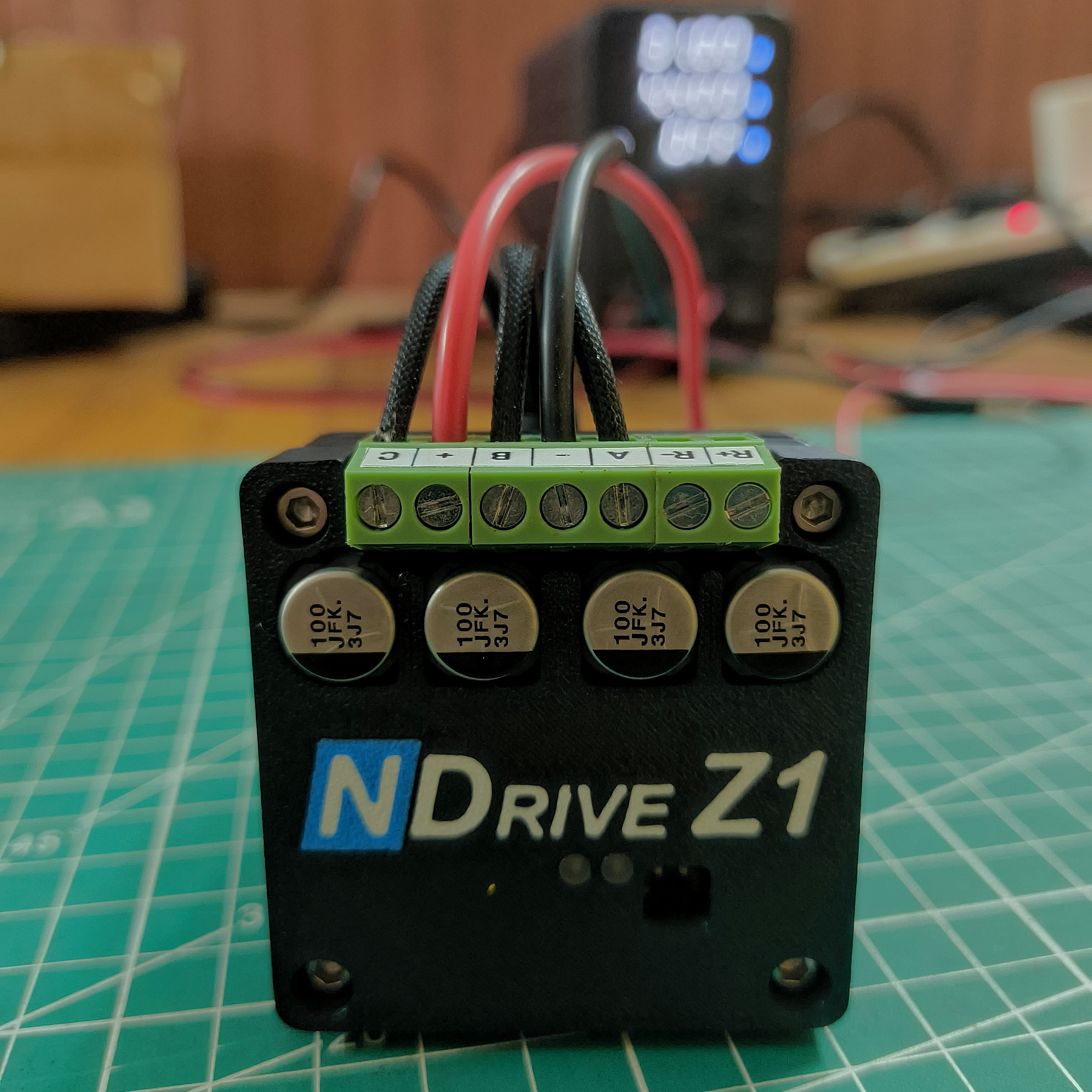
Motor Phases and Power Connected to NDrive Z1. tip- Make all electrical connections with the power supply switched off to avoid accidental shorts or damage.
- Do not connect or disconnect CAN cables while the NDrive Z1 is powered on. Ensure the driver is completely powered OFF before handling CAN connections to prevent hardware damage.
- 5
Communication:
Connect the NDrive Z1's CAN bus interface to the NLink Adapter using a 2-pin JST PH connector. The NDrive Z1 has a daisy-chainable CAN bus with two ports. Since only two devices are connected(NDrive and NLink), turn on the termination resistor switch in both NDrive and NLink. Refer to the DIP Switch settings.
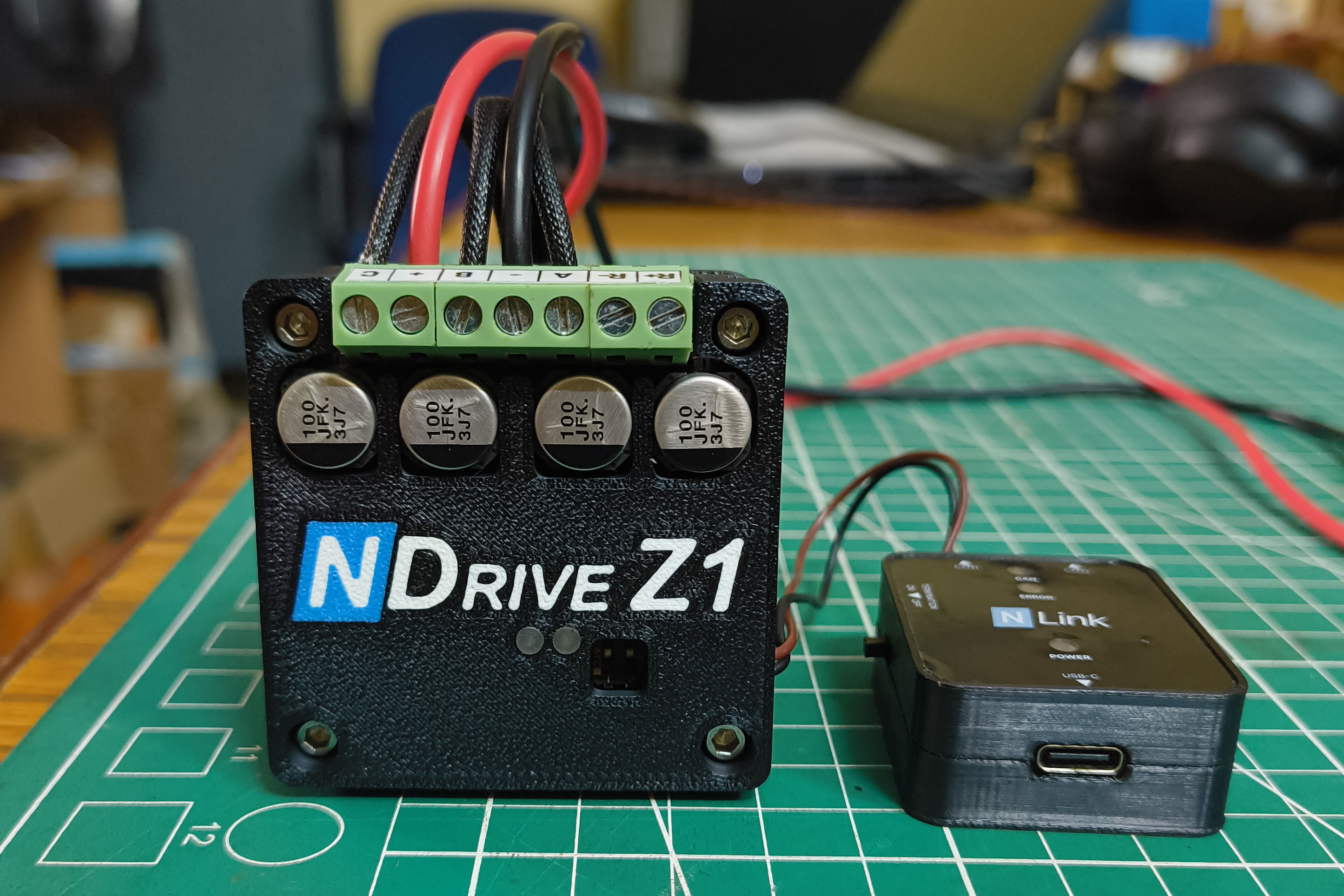
NLink Adapter Connected to NDrive Z1 - 6
Connect to PC:
Plug the NLink Adapter's USB-C port into your system.
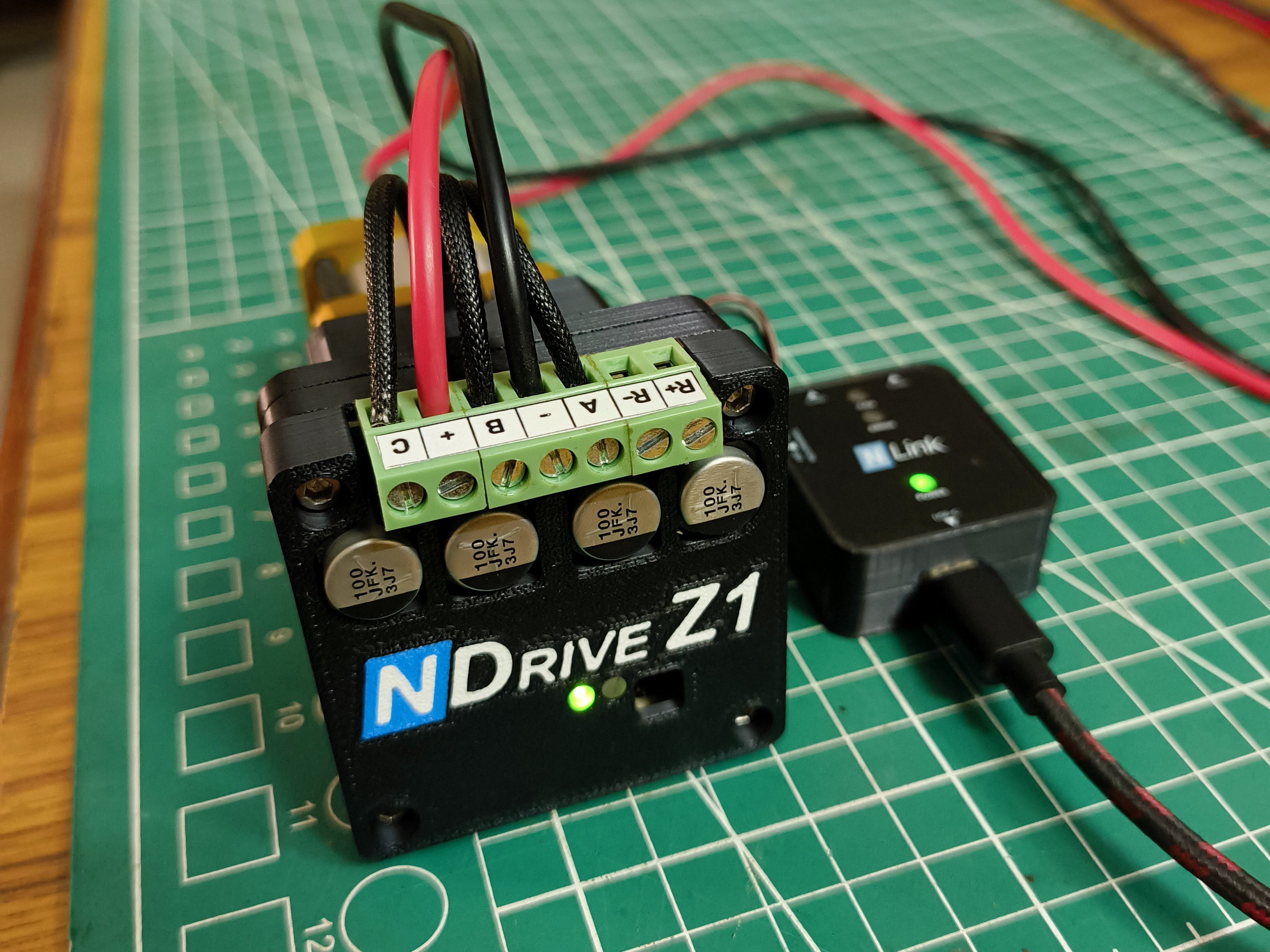
Final Assembly of NDrive Z1 with the Geared 3536 BLDC.
Configuring the NDrive Z1
The NMotion CLI is a command-line interface used to configure and manage NMotion devices. It supports setup, calibration, and testing of the NDrive Z1 through simple terminal commands.
- 1
Install the NMotion CLI Tool:
Download and install the latest NMotion CLI tool on your computer.
- 2
Powering up the NDrive:
Turn ON the power to the driver. The COM LED (yellow) should blink during boot-up, indicating normal startup. If the LED does not blink, ensure that the DIP switch is configured to RUN mode.
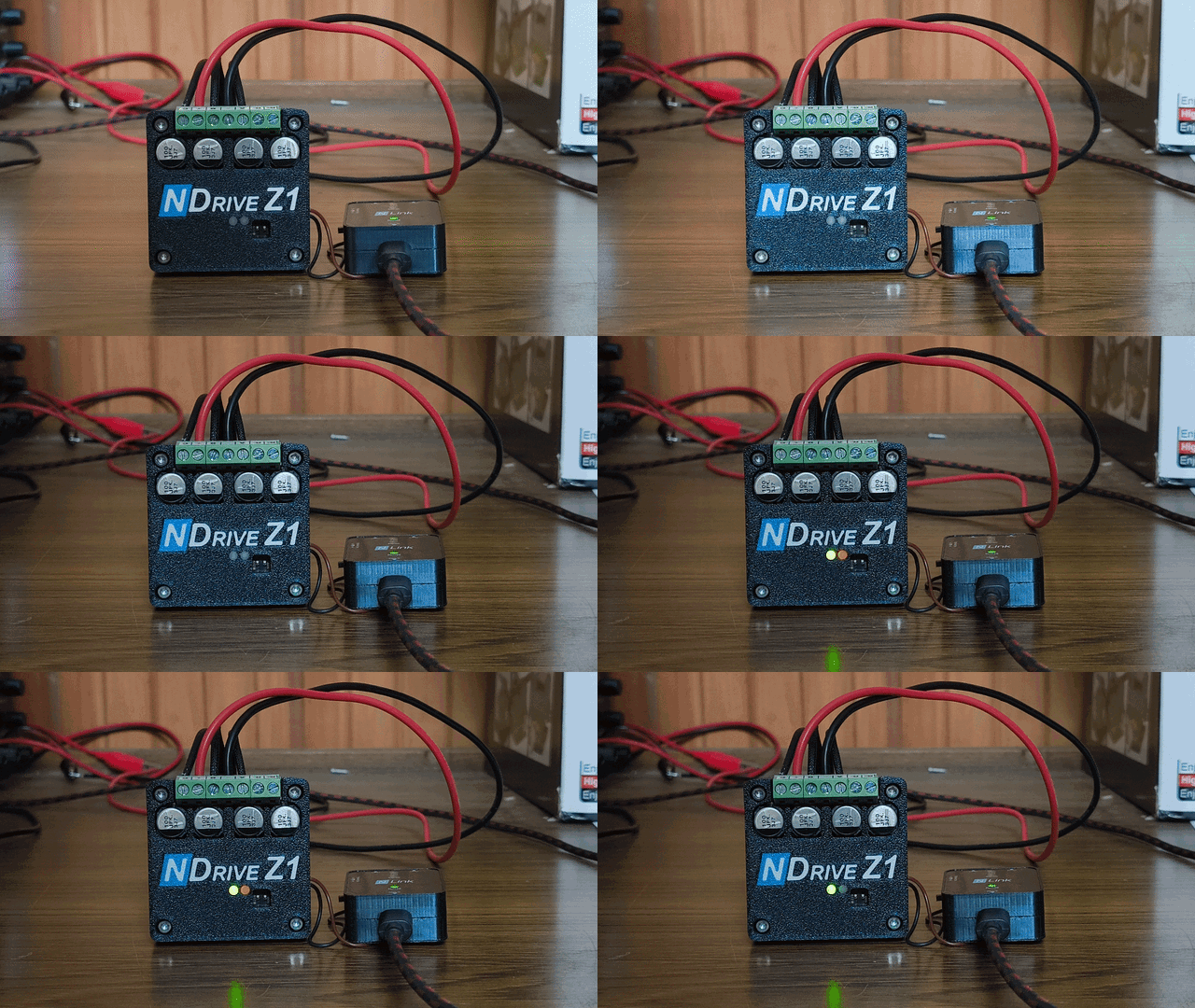
Powering up NDrive Z1 - 3
Connect via NLink and Launch the NMotion CLI:
Plug the NLink adapter into your PC using a USB cable. Open a terminal and start the NMotion CLI.
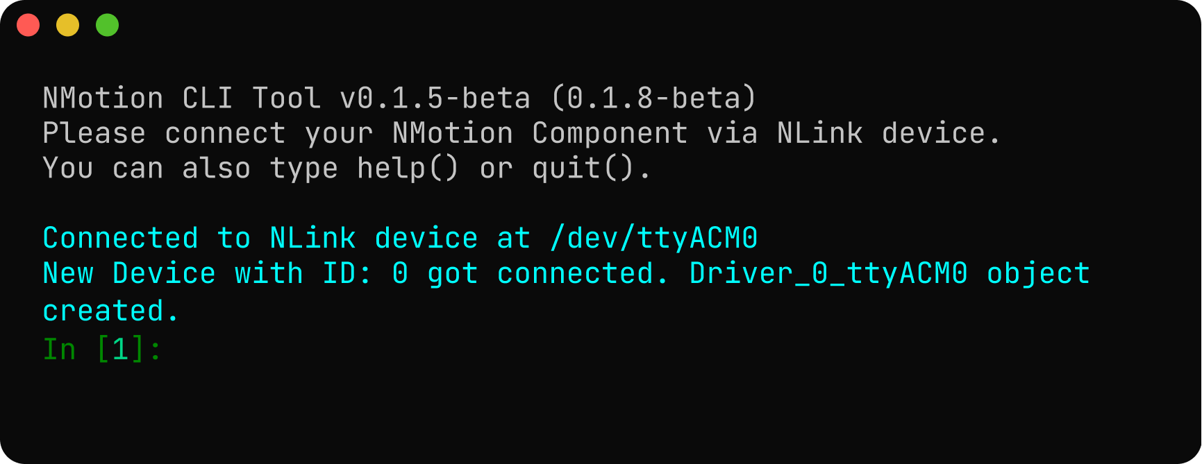
If everything is set up correctly, the NLink will be connected as a USB device, and its corresponding object will be created successfully. If the expected output is not displayed in the CLI Tool, refer to the troubleshooting guidelines to identify and resolve the issue.
When the driver is powered ON, the CLI automatically detects it and creates a corresponding object (e.g.,
Driver_0_ttyACM0) based on its default CAN Node ID. - 4
NMotion CLI API Functions
The configuration can be written using set commands and can be read using get commands. Refer API Documentation for more details.
- 5
Configure CAN Bus:
It is crucial to assign a unique CAN Node ID to the driver, especially if multiple devices are on the CAN bus. The default ID is 0. You can change it using the
setNodeId()function.noteSetting the CAN Node ID will cause the driver to disconnect and reconnect as a new object name in the CLI (e.g., from
Driver_0_ttyACM0toDriver_10_ttyACM0if you set the ID to 10). To save the new node, save the node ID using thesave_configuration()function. After the command, the driver will save and reboot.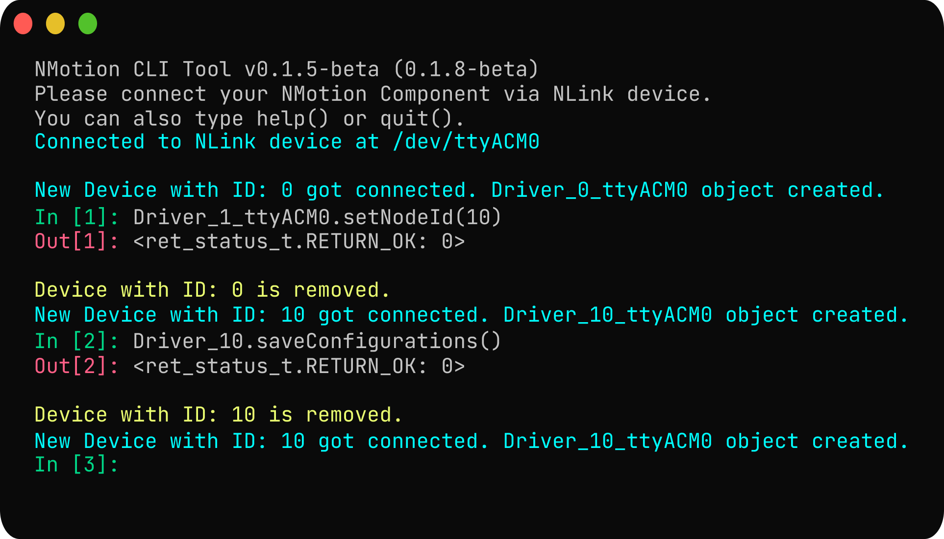
- 6
Power Configuration:
Configure the under-voltage and over-voltage trigger levels. The driver will trigger a voltage trip error if the voltage goes below the under-voltage trip level and above the over-voltage trip level. The under-voltage trigger level is configured as 10V, and the over-voltage trigger level as 25V.
No brake resistor is used in this configuration, so the regenerative current should be set to a suitable value (default: 8 A). Configure the regenerative current to 8 A using
Driver_10_ttyACM0.setRegenCurrentTripLevel(8). Also disable the brake resistor usingDriver_10_ttyACM0.disableBrakeResistor().
- 7
Motor Configuration:
Configure the motor parameters such as pole pairs, kV rating, and current limit using
Driver_10_ttyACM0.setMotorParameters(pole_pairs, kV_rating, current_limit). For the 3536 910kV BLDC motor, the pole pair is set to 7, and the kV rating is set to 910. Set the current limit to 25A.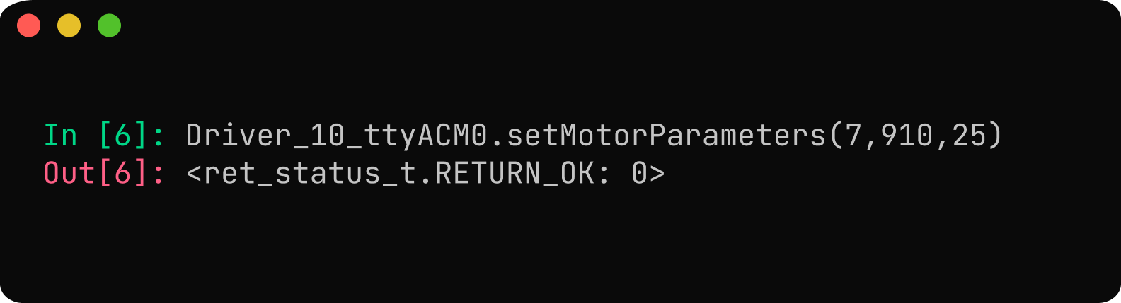
- 8
Encoder Configuration:
Use
Driver_10_ttyACM0.configureMotorEncoder(1,16384)to configure the onboard absolute encoder as the motor encoder. The encoder_type for the onboard absolute encoder would be 1 (TYPE_ONBOARD_ENCODER). The onboard encoder's resolution is 14 bits. Remember to save the configuration for the encoder settings to take effect.
- 9
Calibration Configuration:
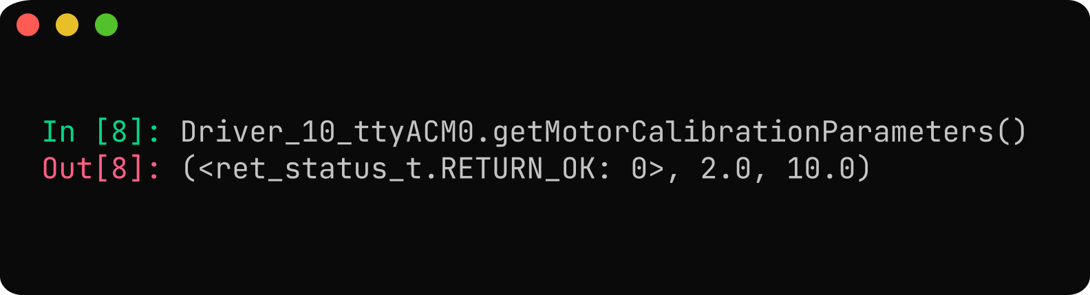
For the 3536 910kV BLDC motor, set the calibration voltage to 2 V and the calibration current to 10 A to ensure safe operation and accurate phase parameter estimation during the calibration process. Refer setting calibration parameter.
- 10
Save Configuration:
After setting all parameters, save them to the driver's non-volatile memory using
Driver_10_ttyACM0.saveConfigurations(). This ensures settings persist after reboot. Saving triggers a reboot. Be mindful that the non-volatile memory has a limited number of write cycles, so avoid saving too frequently.
Calibrating NDrive Z1 with Motor
Before running the calibration sequence, ensure that the motor is free to move and all loads are disconnected. Also, ensure that the motor and power connections are properly connected and the driver is properly mounted.
Initiate the calibration sequence by using Driver_10_ttyACM0.runCalibrationSequence() command.
During the calibration, the NDrive Z1 measures motor phase parameters, determines the encoder offset, and verifies the configured pole-pairs and counts per revolution (CPR). The motor will draw some current and emit a short beep during the inductance measurement phase, followed by slight rotations in both directions for encoder offset calibration.
If no errors occur, the NDrive Z1 has been successfully calibrated with the motor. Save the calibrated configuration to complete the process. Your NDrive Z1 is now ready for motor control.
If any error is triggered, the error LED (RED) will be ON. You can check the specific error code using Driver_10_ttyACM0.getErrorCode() function and then refer the Error Handling section for troubleshooting the issue.
Tuning PID Gains
By default, the the VelocityControllerGains is set to (0.075, 0.33) and PositionControllerGain is set to 60. For the 3536 910kV BLDC motor, configure the control loops using the recommended values. Set the position loop with setPositionControllerGain(60) and configure the velocity loop using setVelocityControllerGains(0.03, 0.15). These values provide a solid baseline for stable and responsive motor control. For more detailed tuning guidance, refer to the PID tuning blog post.
Setting Gear Ratio
Set the gear ratio of the gearbox using the setGearBoxParameters() command. The ratio is defined as output / input, and in this example the S38 P223 gearbox has a ratio of 21. Applying this value ensures that all reported position and velocity readings correspond to the gearbox output rather than the motor shaft. This is important because it allows the NDrive Z1 to calculate and command motion based on the actual output shaft, providing correct scaling for position, speed, and any operation that depends on precise output-shaft movement.
Operation
After calibration, the motor can operate in various control modes such as position, speed, and torque. Here, the motor is commanded to move to an angle of 180 degrees at a speed of 60 degrees per second.

Ensure safe and reliable operation of the motor controller by monitoring the error LED and checking the error codes reported by the controller.
By following this tutorial, the NDrive Z1 can be configured and calibrated to control the geared 3536 BLDC, with position and velocity referenced to the gearbox output.
For more details, check out our documentation or reach out to our support team!
 NMotionTM is a sub-brand of Nawe Robotics